An RFduino is a tiny fingertip sized Arduino that features wireless Bluetooth. An assortment of tiny stackable shields are made available so that you can make a number of cool projects. To learn how to set up an RFduino, see Setup Your First RFduino.
I have been wanting to make a simple servo controller project lately and I thought that this little package is the coolest thing because it is tiny, wireless and I can power it with a USB power pack which makes it completely self contained and it will be controlled wirelessly using an Iphone.
What You Need
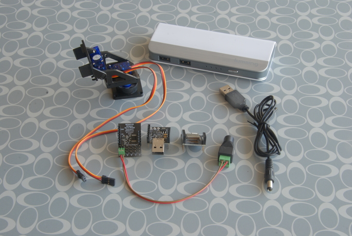
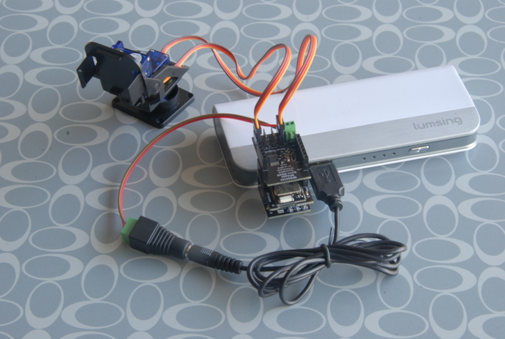
This little project requires the basic wireless RFduino plus their USB and servo shields. The USB shield not only provides the most convenient way to apply power, but also provides a way to download sketches (programs) into the controller. The Servo shield can control up to four servos.
I also need some servos to drive and I found a neat little Mini Pan-Tilt Kit for under $20 from Adafruit. You can use any servos that you wish in your project. To power it all, I decided to use a USB Power Bank as a battery. I happened to find one that suits my need in Lumsing. I wanted to keep my cabling simple and off the shelf so I got a usb to barrel jack cable, and a Female DC Power Adapter which I also picked up from Adafruit.
Program the RFduino
Connect the RFduino and USB shield together and plug into your computer.
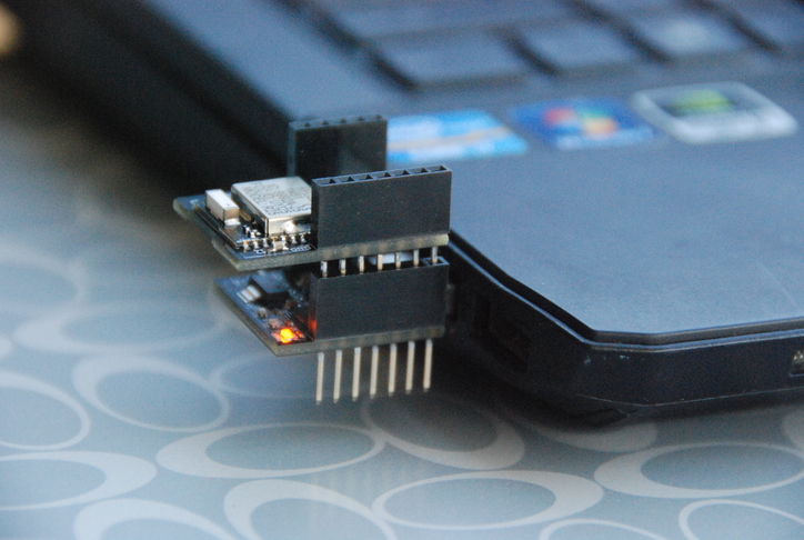 Open the Arduino IDE. Follow the RFduino Setup post if you don’t know how to do this. Open the sketch from File/Examples/RFduinoBLE/Servo in the IDE.
Which basically looks like this:
1 2 3 4 5 6 7 8 9 10 11 12 13 14 15 16 17 18 19 20 21 22 23 24 25 26 27 28 29 30 31 32 33 34 35 | |
And download the the servo sketch into the Arduino.
Some Assembly Required
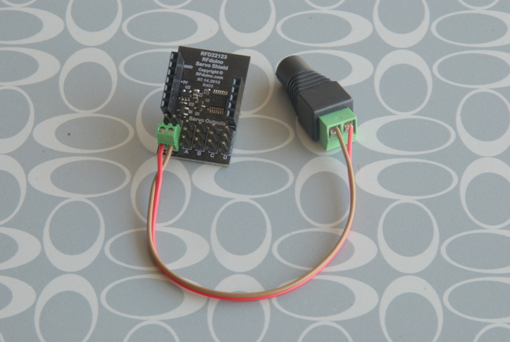
Strip two small pieces of wire and connect the +v(s) and gnds on the terminal blocks of the servo shield to the ones on the DC Power Adapter.
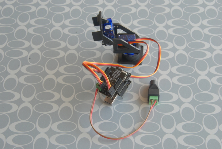
Connect the Servo Wires to the RFduino Servo Shield and then connect the Servo Shield to the RFduino.
- Brown is Gnd
- Red is +5v
- Orange is Signal
Connect Power
Plug both the RFduino and Servo Shield power to the Power Bank.
Get the Iphone App
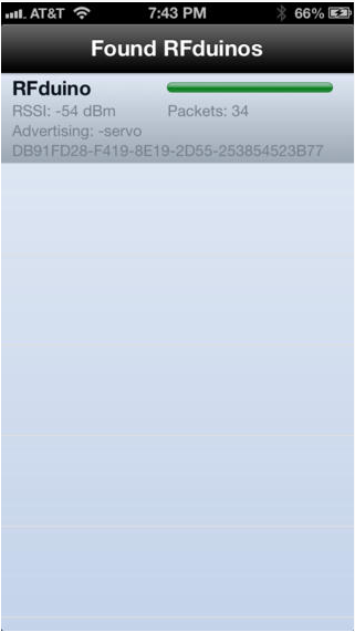
Go to the App Store on your Iphone and search for RFduino. Find the Servo app and install it. Once installed, turn on the Power Bank, then open the Iphone Servo App. The app should discover the RFduino and display it in the app. Click on the found RFduino and it should open a control panel.
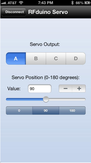
You should be able to select servo channels and then move the slider and your new Servo System should respond.
My servo system is acting a little sick as you can see from the YouTube video. What is going on?
Ok, after a bit of digging around, I discovered that although the RFduino BLE and the Servo shield both work well by themselves, they do not work well together. You see, PWM waveforms are generated by two counters. One for pulse width and the other for pulse frequency. In this implementation, the counters used are not actually on the servo shield but internal to the RFduino itself. You can see from the RFduino Servo Shield Schematic that there are no counters or PWM generator but only a quad amplifier.
When the BLE is used, the interrupts somehow corrupt the counters intended for the PWM signal which causes a great deal of unacceptable jitter. This is something the RFduino folks should fix, but in lieu of that happening, the best solution is to get a third party servo shield with its own PWM generator i.e. its own counters. In that way, the controller would only need to write two registers (width, period) per servo. Adafruit provides such a board which I have and will soon implement, but its out of scope for this post.
*Note: Another possible solution is to use the RFduino and servo shield without the BLE, but then I would lose my wireless capability, which is my sole reason for using the RFduino.
Conclusion
This post shows you how to connect an Iphone to and RFduino and servo shield. I love how this project is so self contained. You can easily imagine how the parts can easily fit into a robotic system which is not tethered to any stationary devices for power or control. Although this project proved to be flawed, if an improved servo shield was used, the project would be quite successful. Maybe I will do this and update this writeup in the future, but for now… On to my next robot project.
Do cool things.


